- Connections
- Softwere
- Troubleshooting
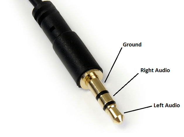
AUX schematic:
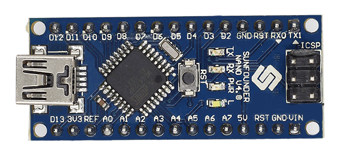
An example for an Arduino board:
As you can see from the AUX schematic above, the basic AUX connector contains 3 separate parts: Ground, Left audio, and Right audio. It is important to connect the Ground part to a "GND" labled pin on the Arduino board. The other Two lines: Left audio and Right audio; should be connected to an analog pin on the Arduino board. Those pins are usaully labled with the letter A. (Connect the left and right audio parts to the same analog pin)
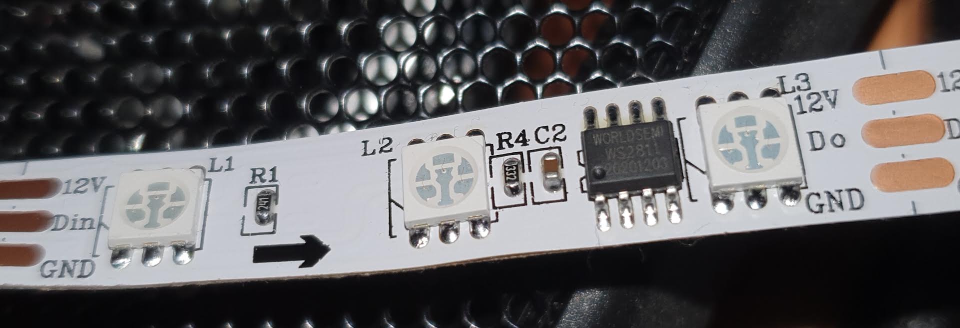
An example of an addressable LED strip (the one I'm using):
This part is a bit more tricky but definitely achievable. We need to connect the LED strip to an external power supply as well as to the Arduino board.
- Please note that electricity is very dangerous. Do not attemp anything that you are not sure is safe
First, look at your LED strip to determine what Voltage it requires. My LED strip, for example, requires 12v. Chances are you have a supplier of that voltage lying around from an old router or something but they are not very expensive and relatively easy to find.
- Note that it needs to be DC and not AC
Now all that's left is to connect it to the LEDs. to do this, determine which part of the power supplier cable is the possitive and which is the negative and connect the possitive to the possitive part (in my case it's the part labled "12V") on the LED strip and the negative part to the part labled "GROUND".
Connect the remaining cable of the LED strip, which shoud be labled "Din" or "D" or "DATA", to one of the Data pins on you Arduino board. And also connext the "GROUND" cable of the LED strip to one of the "GND" pins on the arduino. This is important for science reasons.
Downoad Arduino IDE: https://www.arduino.cc/en/software
Add the FastLED library, here's a good tutorial: https://www.ardu-badge.com/FastLED
And, of course, download the .ino file in this repository.
Now, to make it work, you'll need to change a few parameters according to how you set your LED strip up:
- Make sure that you set the pin constants to the correct pins to which you connected the "DATA" to the LED strip and the Analog pin to the one you connected the AUX output to
- Look at one of the chips on your LED strip to determine which type it is and write it in the "setup" function. For example, in my case, as you can barelly tell by the photo, the type of chip I have is "WS2811"
- You will also need to find out the order of colors the LED strip reads. It can be "RGB" or "GRB" ... In my case it's "BRG". The only way to find this out for sure is trial and error.
If you're using Windows 10 you'll probably have to install these drivers in order to program Arduino Nano: Drivers
If the input from your AUX cable isn't solid 0 when not playing music, try connecting the Arduino power supply to the same system to which the AUX is coneccted. Generally speaking, in my opinion, the best way to set this up is to connect the AUX and Arduino to a TV streamer. Those often send audio signals to both AUX and HDMI ports at the same time, making it ideal for this project. You also use one of these
If you run into any other problems you can contact me at giladfisher13@gmail.com