ESP32-CAM adaptation for use as an FPV camera with LEGO Technic / Power Functions. This repo includes PCB files and modified code from CameraWebServer. Main differences include:
- Lowest possible camera resoulution for highest possible framerate. Maximum FPS is dependend mainly on WiFi signal level and the hub's ability to provide enough electrical power to the camera module.
- mDNS so you can reach the video server by hostname
This PCB and sketch can be also used as an adapter to control a GeekServo with a Mould King Power Module 4.0. You can use just the servo functionality without connecting the OV2640 camera module (but ESP32-CAM board is still required).
YouTube demo video - GeekServo
- The camera module consumes quite a lot of electrical power and is very sensitive to undervoltage. Most LEGO compatible Power Functions remote hubs are able to provide required power, however if your vehicle also contains a lot of motors, you can drain the hub's battery very fast or even burn it. Think of a connected cammera as if it is a constantly rotating L-motor at full speed.
- The module becomes very hot very quickly. Do not touch it while it is working and immediatly after powering off.
- ESP32-CAM board
- (optional - only needed for the FPV) OV2640 camera module
- ESP32-CAM-MB or other USB-Serial adapter for uploading the sketch
- 9V to 5V buck converter (N7805 or similar, capable to deliver 5V/1A for the camera module). Do not use older LM7805 for powering the camera since it is very inefficient - the power from the hub will be wasted, resulting in 1) even more extreme heating 2) quick battery drain 3) lower FPS due to undervoltage 4) possible damaging of the hub/battery. If the board is used just as a GeekServo adapter (without enabling the FPV functionality) you can use a simple LM7805, which is sufficient for a servo.
- 30x70mm PCB breadboard or factory made PCB with files from this repo
- 2x female 8-pin headers
- Power Functions extension cable
- (optional) Any kind of 2.54 4-wire connectors to solder on PCB and extension cable to make it detachable.
- (optional - only needed for GeekServo adapter) 2x 1 kOhm and 2x 2.2k Ohm resistors
- (optional - only needed for GeekServo adapter) 3-pin male pins for attaching the GeekServo
- Some wires and other soldering accessories

 If you experience power related issues, try adding capacitors
You can order a factory made PCB to reduce soldering. Production files are located in PCB directory of this repo.
ATTENTION the PCB silkscreen has an error: 2K and 1K resistors need to be swapped!
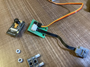
After soldering the components, the board should look like this:


Before soldering, please review the pinout of the Power Functions Connector Power Functions

- Install ESP32 Boards in Arudino IDE https://docs.espressif.com/projects/arduino-esp32/en/latest/installing.html
- Download sketch code from this repo
- Install ESP32Servo library dependency
- Review the defines in the beginning of the main CameraBrick.ino. You can enable FPV and GeekServo functionality independently or use both at the same time.
- Update secrets.h with your WiFi credentials
- (optional) Update esp_camera_server.h if you are using a different board or camera model. AI Thinker & OV2640 are the default options
- Set board to ESP32 Dev Module and enable PSRAM in Tools menu
- Upload the sketch to ESP32CAM either using ESP32-CAM-MB or USB-Serial adapter
There are two main options
- Open http://fpvbrick.local in desktop or mobile browser
- Open http://fpvbrick.local:81/stream in video player that supports streaming (VLC media player for example)