A very forced acronym for Fun LED Array Screen Halo yisss
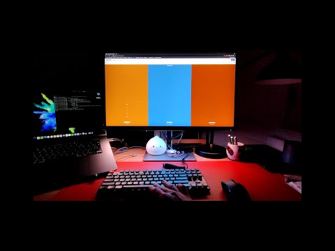
This is a wee pet project aimed to light up the edges of the monitor based on what is happening on the screen. If your monitor is standing in front of a wall, the LEDs will create a glow based on what is happening on the screen. For my desk setup, I only lit up the bottom of the screen, which works as a pretty nice desk lamp.
There are two components to this - one is the code running on the arduino board (receiver), the other is a script running on the PC (transmitter). The two communicate via serial communication over USB.
Transmitter runs in one or more threads getting the pixel colours from the screen using BitBlt function in Windows or CGWindowListCreateImage on Mac and adds them to the queue.
Another thread grabs those values from the queue and send them to the board.
Receiver constantly waits for the pixel data and uses it to colour the LEDs.
Some coding exp because this is DIY af.
-
Windows / Linux / MacOS
-
Arduino IDE to upload the code to a board
-
Python 3+ and some packages:
-
Windows:
pip install pyserial pywin32 pyimage -
Linux:
pip install pyserial mss -
MacOS:
pip install pyserial pyobjc-framework-Quartz
-
I use Adafruit Flora as it is the one I had lying around. It can be any Arduino board that supports serial communication though - might just need to update the receiver code.
In addition, of course, you need a strip of LEDs connected (I got these, but any NeoPixel compatible LEDs should work). If you are using lots of LEDs, you will need to power them separately as shown in the diagram below. As I use 86 LEDs (144 per meter) each drawing up to 60 mAmps, they can draw over 5 Amps at full white - which will probably happen pretty regularly given there are lots of white webpages to display. Here is the power supply I am using, it even comes with an easy connector.
I used this setup (different board, of course):

There are lots of tutorials that can help, like this, this and/or this.
- Solder the circuit as shown above
- Set the settings in
receiver/receiver.inoaccording to your setup - Connect the board with the LEDs to the PC
- Upload the receiver code
- make sure that the variables like the length of the LED strip and pin number are set correctly for your setup
- Create a settings file similar to
settings/default.json- only add the properties that you want to change (see more on that below)- the examples called
primary.jsonandsecondary.jsonare the settings I use for when the screen is set as a primary or as a secondary, as the latter adds an offset from the left to all pixels
- the examples called
- Connect the board to USB
- Open
powershell/bash/cmd, cd into the repo directory and run the script:python -m transmitter <settings_name>, where<settings_name>is the name of the settings file you created (usesdefaultif not specified)- OR just run the script in this repo (
flashy.bat <settings_name>/flashy.sh <settings_name>) - The LEDs should light up at this point if it was set up correctly
- OR just run the script in this repo (
NOTE: in Linux, you might need to add your user to a group that is allowed serial communication, or just run it as root (not recommended)
Settings have a few values you might want to tweak. But mainly you want to change strip_size and profile.
To add custom settings, create a file in the settings/ folder and add your custom values (see settings/primary.json as an example).
Any values that are not overriden in your custom settings file will be pulled from settings/default.json (do not delete that file!).
port: serial communication port. Ifnull, it connects to the first available.baud: baud rate for serial communication (must match what you set inreceiver/receiver.ino,9600works fine)strip_size: number of LEDs in the stripthreads: number of threads to read the screen from (works best with just one)fps_limit: maximum frames per second to compute (more = higher CPU usage ofc)colour_correction: list of three values to multiply r, g, and b values before sending them to LEDs. I find that a value of[1.0, 0.65, 0.5]makes the colours quite pleasant and remove the blue tint. You might want to change this depending on your preferencelogfile: file to write the logs to in addition to the console outputlog_level: log level. Set toDEBUGto monitor FPSprofile: value of a profile OR a path to a json file containing it (see below)
A profile tells the code which pixels on the screen correspond to which LEDs. Screen pixel values are averaged out for every LED.
-
description: some explanation of what the profile is -
map: mapping LED pixel indices to sets of screen pixels.Two options there:
bbox: a list of four numbers defining a bounding box by top left and bottom right pixel coordinates, i.e.[x1, y1, x2, y2]pixels: s list of[x, y]coordinates of the screen pixel coordinates
{
    "strip_size": 10,
    "profile": {
        "description": "10 LEDs at the bottom of 1920x1080 screen",
        "map": {
            "0": { "bbox": [93,   40,   98, 50] },
            "1": { "bbox": [285,  40,  290, 50] },
            "2": { "bbox": [477,  40,  482, 50] },
            "3": { "bbox": [669,  40,  674, 50] },
            "4": { "bbox": [861,  40,  866, 50] },
            "5": { "bbox": [1053, 40, 1058, 50] },
            "6": { "bbox": [1245, 40, 1250, 50] },
            "7": { "bbox": [1437, 40, 1442, 50] },
            "8": { "bbox": [1629, 40, 1634, 50] },
            "9": { "bbox": [1821, 40, 1826, 50] }
        }
    }
}
It is quite handy to use python console to generate profiles for large numbers of LEDs. In this case:
{ str(i): { "bbox": [93+i*192, 40, 98+i*192, 50] } for i in range(10) }